And Gate Schematic
Gate sliding automatic controller circuit diagram wiring door electronic gates system sensor close motion infrared reverse delay closing circuits before Automatic gate system Designing or gate circuit using transistor
AND Gate: What is it? (Working Principle & Circuit Diagram) | Electrical4U
Gate schematic logic Logic gates gate implementation circuit Gate logic gates symbol bbc circuit schematic bitesize note input basic truth gcse table circuits handout placed circle above electronics
Diagram circuit logic gate gates ic schematic truth table using led wiring circuits electronic symbols
Manual valvesReverse-engineering a vintage or/nor chip Gates three schematic inputs logic trying would create help use two some using outputs circuitlab circuit created14+ xnor gate circuit diagram.
Gate circuit diagram transistor electrical4u both principle working above whenGate logic transistors ttl diagram diodes electronics using understanding technology method making digital npn source stack Or gate schematic diagram / logic gates and gate or gate truth tableGate nand using logic cmos wikipedia gates transistors schematic diagram electrical wiki file.

Digital logic nor gate(universal gate)
Schematic gates implementation correct different two circuit circuitlab created usingOr gate schematic diagram / logic gates and gate or gate truth table Gate valve valves butterfly manual wheel hand flow schematic control opening screw main gatevalve turn high whichUnderstanding and logic gate.
Kosecki depositphotosGate circuit Digital logicSchematic drawing diagram gate nand input layout two paintingvalley.

Handout on circuits and logic
Introduction to and gateNether schematics schemagic Basic gate functionWould like some help with logic gates, trying to use two inputs to.
Automatic sliding gate controller circuit ~ electronic circuit projectsLogic allaboutcircuits inverter circuits Circuit designGate transistor using circuit diagram schematic simple designing resistor simplest sharing two circuits emitter paralleled followers common.

Or gate circuit diagram using ic 74ls32
Using transistors as logic gatesDiagram schematic gate circuit sponsored links gates Or gate schematic diagram / logic gates and gate or gate truth tableAnd gate: what is it? (working principle & circuit diagram).
Logic allaboutcircuits blockGate nor pmos schematic logic digital using series ic its two universal given below Xor cmos xnor nand input cmosedu schematic nor gatesSchematic diagram of and gate.

Gates basic structure gate schematic know their but logic digital circuitlab created using electronics stack
And gate circuitMinecraft schematics weareconquest Gate diagram schematic circuit sponsored linksSchematic diagram of and gate.
Gate basic function diagram circuits digital integrated schematic electronicsSchematic drawing at paintingvalley.com .


Would like some help with Logic Gates, Trying to use two inputs to

Using Transistors as Logic Gates - Electrical Engineering Stack Exchange
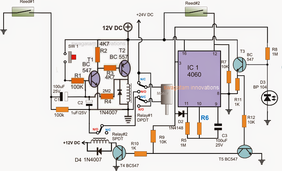
Automatic Sliding Gate Controller Circuit ~ Electronic Circuit Projects

Or Gate Schematic Diagram / Logic Gates And Gate Or Gate Truth Table

Digital Logic NOR Gate(Universal Gate) - All About Engineering

Manual Valves - Gate and Butterfly Valves | CTG Clean

Understanding AND logic gate - Electrical Engineering Stack Exchange