4-20ma Wiring
20ma plc analog sensor interfacing sensors scada flexs q3 smart internet interface ma current industrial output Wiring 20ma sensors 20ma wiring plc siemens
Why We Preferrably Use 4-20mA Over 0-10V & 0-20mA As A Analog Signal
Why we preferrably use 4-20ma over 0-10v & 0-20ma as a analog signal 20ma fundamentals loads Interfacing to 4-20ma analog sensors with the flexs q3 smart plc
Isolated 4-20ma to 0-5v 0-10v signal conditioner
Need more current than 4 ma in 4/20ma loop current4 to 20 ma current loop output signal Basics of the 42-wire 4-20ma loop simulator signal generator.
Wire 20ma loop current ma transmitter difference using vs power source ti e2e transmitters between than need electrical amplifiers linear4-20ma – 2 wires – automation expert Loop control ma positioner current loops 20ma valve transmitter flow process controller position smart dcs feedback connectedExample 4-20ma thermistor transmitter wiring diagram.

20ma transmitter wiring thermistor diagram example circuit loop current measure
4-20 ma current loop – widgetlords electronics4-20ma output signal 4-20 ma process control loops4 20ma input wiring.
Wilbo666 / 4-20ma20ma 5v 20ma wire powered field loop wiring power4 to 20 ma current loop output signal – sensorsone.
Passive 4-20ma current loop simulator current generator
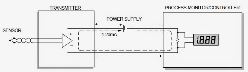
4-20 ma current loop20ma 10v analog signal over why loop current use circuit typical process preferrably control send location figure 20ma wires automationD105: connecting the sensor with a 4-20ma current loop / main / smart.
Ma wire transmitter loop current spi 8ai pi20ma converter signal loop convert vdc rs232 5vdc resistor ohm volts sensorsone 20ma output loop transmitter circuit sensorsone20ma output indicator analog wire wiring digital plc diagram 5vdc ammeter shows into.

Analog output 4-20ma/0-5vdc wiring w/ digital indicator
20ma simulation passiveLoop current 20ma diagram control basics circuit power instrumentation supply resistance wires four basic through Wilbo666 / 4-20ma20ma current smart d105 connecting maic.
20ma wiring voltage current 5v arrangements .


4-20mA Output Signal | Core Sensors

Interfacing to 4-20MA analog sensors with the Flexs Q3 Smart PLC

wilbo666 / 4-20mA

4-20 mA Process Control Loops | DCS Control Loop | Inst Tools

Isolated 4-20mA to 0-5V 0-10V Signal Conditioner

Analog Output 4-20mA/0-5VDC Wiring w/ Digital Indicator - Arlyn Scales

4-20 mA Current Loop | Basic Fundamentals

D105: Connecting the sensor with a 4-20mA current loop / Main / smart